
SPEED
QUALITY SUPPLIERS
EASY NAVIGATION
QUICK RESPONSES
DIRECT SHIPMENTS
GLOBAL SUPPORT
EXCELLENCE
QUALITY SUPPLIERS
PROMPT SERVICE
SATISFACTION IS
#1 PRIORITY
ECONOMICS
LOWEST PRICES
FREE FREIGHT
QUICK DELIVERIES
KNOWLEDGE
FACTORY TRAINED
OTJ EXPERIENCE
ENGINEERING SUPPORT
How to Properly Size a High-Pressure CNC Coolant Pump System
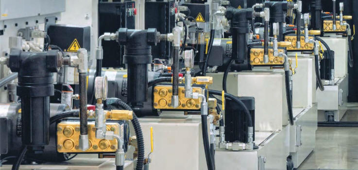
High-pressure coolant on a CNC machine clears chips, stretches tool life, holds tolerance and improves finish. A lot of systems using dynamically sealed pumps fall short on pressure, flow or uptime.
Piston, plunger and multi-stage centrifugal coolant pumps use dynamic seals. Those seals wear, leak coolant and cause downtime. A Wanner Hydra-Cell Pro® is sealless positive displacement pump — no packing or seals — and it will pass coarser solids than sealed designs, enabling coarser filtration.
What follows is the information needed to size the high-pressure Wanner Hydra-Cell Pro pump for a CNC coolant system.
High-Pressure Coolant System Overview
In simple form the system takes filtered, reclaimed coolant and delivers it at up to 2,500 PSIG. Filtration fineness is set by the finest clearance in the loop:
- tooling
- rotary unions
- valves
- the pump
A Wanner Hydra-Cell Pro pump will survive with particles as large as 400 microns. A piston or plunger pump often wants 25 micron or finer filtration. Tooling or the rotary union may still need finer filtration and that will drive the filtration requirement, not the pump. Coarser media means fewer bags, less coolant dumped at change-out, and fewer stops.
Unlike a centrifugal pump, a positive-displacement pump puts out a fixed flow. Pressure comes from resistance — usually the smallest tool orifice in use. Extra flow goes through a sealless pressure regulating valve (PRV) back to the tank. As tools wear or change, the PRV bypasses more or less to hold a set pressure.
Determining Required Flow and Pressure
Variables:
- maximum pressure
- maximum flow
- horizontal or vertical pump
Use the tool maker’s pressure and flow charts when you have them. A generic orifice equation for the largest tool is:
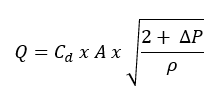
Where:
- Q = coolant flow
- Cd = discharge coefficient (typically 0.65–0.80)
- A = total orifice area
- ∆P = coolant pressure
- ρ = coolant density
That math produces a table like this:
| Orifice Diameter (in) | Orifice Diameter (mm) | Flow at 100 PSI (GPM) | Flow at 300 PSI (GPM) | Flow at 1,000 PSI (GPM) |
|---|---|---|---|---|
| 0.020" | 0.50 mm | 0.2 | 0.3 | 0.6 |
| 0.030" | 0.75 mm | 0.4 | 0.7 | 1.3 |
| 0.040" | 1.00 mm | 0.8 | 1.4 | 2.5 |
| 0.060" | 1.50 mm | 1.8 | 3.2 | 5.8 |
| 0.090" | 2.30 mm | 4.0 | 7.0 | 13.0 |
| 0.125" | 3.18 mm | 7.8 | 13.5 | 24.5 |
Size the pump for the largest tool. The PRV dumps the extra flow when smaller orifices are in use. Size the pump to minimize bypass because too much recirculation heats the coolant, creates foam and wastes power.
The model D10 is the most common model used for high pressure coolant applications. At 1,800 RPM it outputs about 8.8 GPM. Most applications require less than 6 GPM. A 1,200 RPM motor reduces the flow to about 5.75 GPM and you get less bypass, a cooler tank, less foam, a quieter skid and better efficiency.
Some systems put a VFD on the motor and trim speed to pressure so almost nothing is bypassed through the PRV.
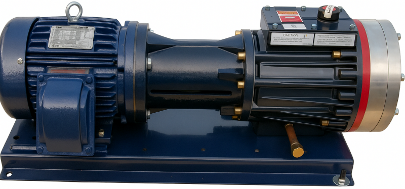
Horizontal vs. Vertical Pump Configurations
Most skids are horizontal, next to the tank, often in an acoustic box. Typical components:
- steel baseplate
- motor
- shaft coupling
- pump/motor adapter
- pressure regulating valve
The adapter holds the pump to the motor, keeps the shafts in line and covers the coupling.
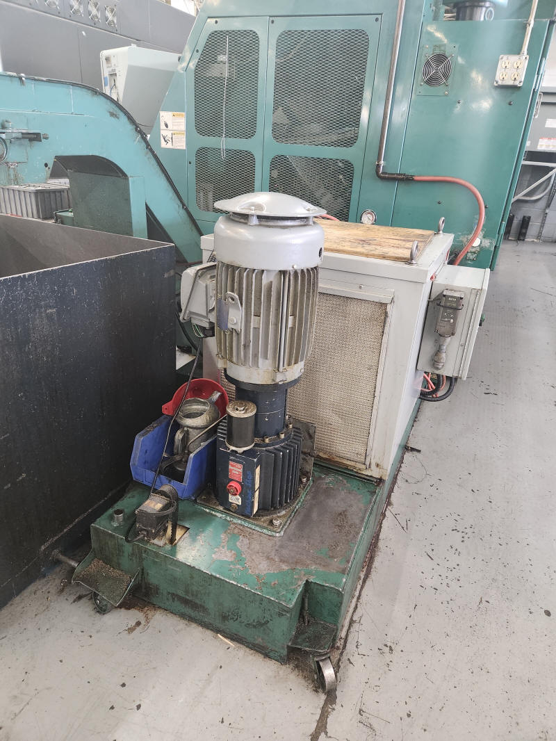
Vertical Hydra-Cell Pro D12 and D17 frames were built to drop in to replace vertical multi-stage centrifugal pumps. A pump base plate is not required, only the pump, motor and coupling. The sealless wet end also removes the seal failures common on those vertical centrifugal pumps.
Important Design Considerations
OEM high-pressure options and turnkey aftermarket packages include filtration, controls and enclosures. Plenty of shops only want the high-pressure pump on filtration they already own. When increasing your system pressure check the following.
1. Verify system pressure ratings
Everything downstream has to be good for the set pressure:
- hoses and fittings
- rotary unions
- valves and manifolds
- filter housings
Every wetted part should match the maximum system pressure.
2. Optimize filtration
The pump will take large particles. Other components may not. Filter to the finest requirement in the loop — not finer. Extra-fine filtration costs more, load faster and can strip additives out of the coolant.
Bag housings are the usual coolant filter design. Displacement balloons cut coolant loss at bag change. Magnetic inserts pull ferrous fines and increase bag life. Both cut coolant buy-back, bag use, disposal and downtime.
3. Route PRV bypass correctly
Bypass should re-enter the tank without entraining air into the coolant:
- oversized return piping
- submerged discharge
- return as far from the pump suction as the tank allows
4. Use enough reservoir volume
Aim for feed tank volume at least four times maximum pump flow. That helps solids settle, air to separate and heat to dissipate. Baffled tanks designs reduce the load on the filer media further.
A Hydra-Cell Pro® sealless coolant pump replaces packed high-pressure designs, opens filtration and ends dynamic-seal leaks on the pump.