Component Breakdown of Sealless High Pressure Pump Skids
 Article-
Components of a high pressure pump skid
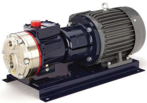
In this article we outline the steps required
to properly size and configure a complete pump skid. You will learn
the information required and the various components incorporated into our
standard pump skid design.
The first thing we must establish is which
model pump we are to provide for a given application and this can become a
complex task which goes far beyond the desired flow rate and pressure.
Water and other relatively non-aggressive (abrasive or chemically) fluids
can be relatively straightforward applications. Pumping slurries,
fluids at extreme temperatures and providing a specific range of flows are
just a few examples that can influence the size of the pump required.
This article will focus on our Wanner™
Hydra-Cell® Pro
sealless positive displacement pumps however the design of these pump skids
and the process of sizing pumps are similar for other types of pumps.
 The easiest way for us to gather the required
data is to use our Internet based inquiry form, as it prompts for all the
information we need and you simply leave the non-applicable sections blank.
Our inquiry form will enable us to not only size your pump but also
configure its materials of construction to maximize performance.
The pump size is a reference to its capacity
and that is typically expressed in gallons per minute (GPM) or gallons per
hour (GPH). We need to know the maximum flow rate required to ensure
the pump is physically large enough to displace that flow rate.
If your fluid is significantly abrasive, hot,
viscous or shear sensitive we might “oversize” the pump. This means we
would suggest a pump having a capacity perhaps as much as double your flow
rate requirement such that the pump would operate at a significantly lower
shaft speed.
Shaft speed and Positive Displacement Pumps
Hydra Cell Pro pumps, like all other positive
displacement pumps, displace a fixed volume of fluid per pump shaft rotation
with the discharge pressure having negligible effect on the volume
displaced. The flow direction through the pump is controlled by
internal check valves and thus the flow rate has a corresponding velocity
across these valves; most importantly between the valve and its’ seat.
Higher flow rates equate to higher velocities through the check valves and
therefore an application involving a significant amount of abrasive material
suspended within the fluid benefits from lower velocities as it slows the
abrasive wear of the check valve components. Materials such as
tungsten carbide and ceramic are sometimes used for the valves to extend
their wear life.
It is a similar rationale when considering the
fluids viscosity and temperature, often operating the pump “slower” is
beneficial.
The required discharge pressure is another
significant factor to consider; the Hydra Cell Pro pump product family includes
pumps for pressures from about 30 PSI to as high as 5000 PSI. (There
are fewer options for pressures over 1000 PSI.) The pressure required,
in conjunction with the maximum flow rate requirement, determines the motor
horsepower required. While some applications benefit from engine, air
and hydraulic motors, for us those are atypical applications, so this
article focuses on electric motors.
Each pump model has a formula associated with
it to determine the horsepower required (HPr). When a flow range is
required, it is important to ensure that the motor selected will provide
sufficient shaft torque at the low-end of the flow range. We have
created a spreadsheet that provides the motor requirements based upon input
of a pump model, minimum flow rate and maximum pressure. The last
aspect of the motor selection is determining if special features, such as
“explosion-proof/hazardous duty” is required; for low HP motors you might
have a choice of single or three phase motors.
The pump model will determine the motor pump
(NEMA) frame required and the importance of this is how we ultimately
connect the pump and motor shaft together.
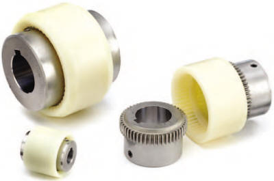
The actual coupling of pump-to-motor is
typically through the use of a “shaft coupling”. A three-piece design
consisting of two geared stainless steel pieces attached to the two shafts
and a sleeve, which synchronizes the two shafts together. There are
some exceptions; we offer a few pump models having “hollow shafts” which can
accept insertion of the motor shaft directly into the pump, eliminating the
need for a coupler and coupling guard. Some customers use belts and
pulleys to convey motor shaft rotation to the pump shaft, controlling the
pump shaft speed by the pulley diameter ratios.
Pump and motor shaft alignment are important,
without proper and stable alignment the coupling will fail and shaft
deflection could damage the pump or motor shaft seals. This applies to
belt-driven systems also to maximize belt wear life. Proper pump/motor
alignment is achieved with an adapter or multi-level pump base, depending
upon the pump size and whether it is direct driven or belt driven.
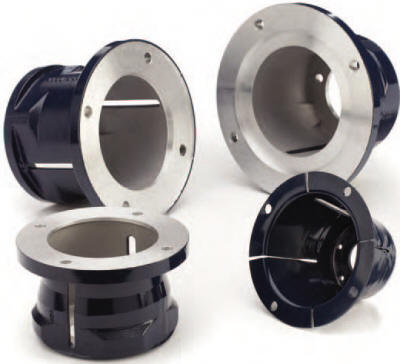
Hydra Cell Pro pumps for flow rates up to 20 GPM
can be attached to the motor to ensure proper shaft alignment. These
“pump-motor-adapters” are an epoxy coated cast aluminum spool with one end
machined to align with cap screws on the shaft side of the pump and the
other end matches-up with the NEMA cap screw pattern. Therefore the
motor size, specifically its NEMA frame, dictates half of the coupling size,
the adapter model and size of the pump/motor baseplate.
If we do not have an adapter for the pump
model or motor size, proper alignment is achieved based upon the design of
the baseplate. Our baseplate models are designed for specific pump and
motor sizes, having pre-drilled mounting holes with threaded nuts welded
onto its underside to enable all fastening to be done from the topside.
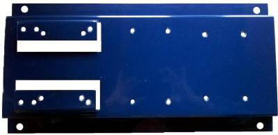
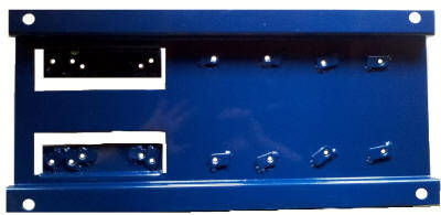
If there is a difference in the mounting feet
to shaft centerlines of the pump and motor, the baseplate will have a
built-in raised pad for the pump or motor such that the shafts will align
correctly; the pads ensure proper vertical and horizontal alignment.
As illustrated on the first page, if you mount
a pump to a motor with an adapter there is no need to support the pump – it
“hangs” off the adapter. It is acceptable if the motor hangs off the
adapter, which might be applicable in some oversized pump applications
requiring relatively low pressures.
It is certainly possible to forgo using a
baseplate with adapter coupled designs and simply attach the motor or pump
to whatever substrate you desire. The Wanner baseplate
design enables adapter-coupled systems to lay on the floor and they have
holes for firmly mounting to a substrate such as a pump pad.
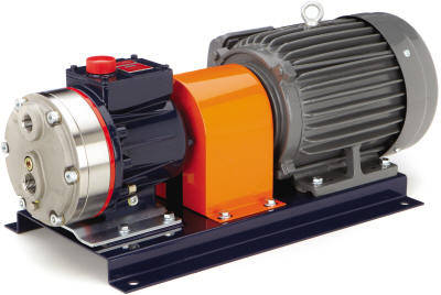
Systems which are “flex coupled”, meaning
without using a pump-motor-adapter, benefit from the Wanner baseplate design
as they’ve already figured-out the appropriate
elevation
for the pump/motor. The baseplates for these systems come with a
coupling guard to prevent accidental contact with the pump and motor shafts.
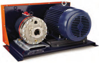
Belt driven systems have a slightly more
complex baseplate design because the motor or pump needs to be able to slide
to maintain proper belt tension, so while belt driven system do not require
adapters and couplings, their guard is larger and the design of the
baseplate more complex, negating any cost savings.
Our proposals are itemized to enable the
customer to consider which items they might be able to source more cost
effectively on their own; they may not need a baseplate or perhaps they have
a local motor distributor providing better pricing. Our itemized
proposals also include common accessories such as sealless pressure
regulating valves, programmable pump controllers (VFDs), pressure gauges,
pipeline strainers and isolation valves.
Our company provides an application based
approach to pump selection, with our decades of experience plus factory
support we provide a reliable solution to the most challenging applications
imaginable.


